Hi there 👋
How can I help you today?
In this project we are going to use Load Cell and HX711 Amplifier with Arduino and Raspberry Pi to build a real time graph system using AWS Services. We are using Load Cell as a sensor since it gives data in high frequency which we can see changing on graphs easily. We have seen these pressure sensing gates at many malls and showrooms, which automatically opens when someone is standing near the door and get closed after that person is gone. Also in hospitals as weight scale.
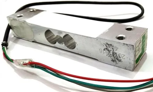
Load cell is transducer which transforms force or pressure into electrical output. Magnitude of this electrical output is directly proportion to the force being applied. Load cells have strain gauge, which deforms when pressure is applied on it. And then strain gauge generates electrical signal on deformation as its effective resistance changes on deformation. A load cell usually consists of four strain gauges in a Wheatstone bridge configuration. Load cell comes in various ranges like 5kg, 10kg, 100kg and more, here we have used Load cell, which can weight upto 40kg.
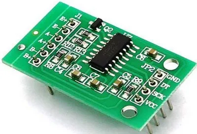
Now the electrical signals generated by Load cell is in few millivolts, so they need to be further amplify by some amplifier and hence HX711 Weighing Sensor comes into picture. HX711 Weighing Sensor Module has HX711 chip, which is a 24 high precision A/D converter (Analog to digital converter). HX711 has two analog input channels and we can get gain up to128 by programming these channels. So HX711 module amplifies the low electric output of Load cells and then this amplified & digitally converted signal is fed into the Arduino to derive the weight.
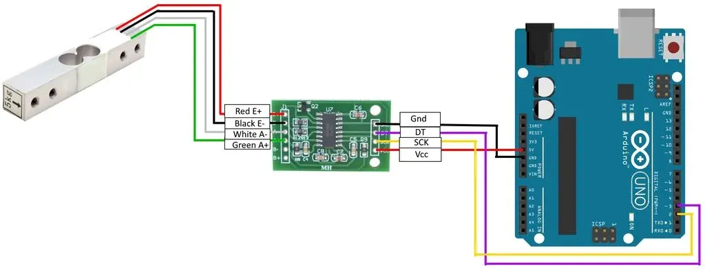
Load cell is connected with HX711 Load cell Amplifier using four wires. These four wires are Red, Black, White and Green/Blue. There may be slight variation in colors of wires from module to module. Below the connection details and diagram:
Connect Load Cell with HX711 and Arduino like below.
Now since our Load Cell is connected to Arduino, we have to code Arduino board to communicate it with load cell.
For this we will have to download HX711 arduino library.
Download the library from the link, and add it to arduino libraries folder.
Below is the code to upload on arduino. (Code will work on any arduino platform if DT and SCK are connected on digital 3,4 pins respectively.)
                  #include "HX711.h"
                  #define DOUT 2
                  #define CLK 3
                  HX711 scale;
                  long int value;

                  float calibration_factor = 166; //-7050 worked for my 440lb max scale. Calbibration factor may be
                  different in your case.

                  void setup() {
                  Serial.begin(9600);
                  scale.begin(DOUT, CLK);
                  scale.set_scale(calibration_factor);
                  scale.tare(); //Reset the scale to 0
                  long zero_factor = scale.read_average(); //Get a baseline reading
                  }
                  void loop() {
                  value = scale.get_units(), 1;
                  if(value<0){ value=0; } Serial.print(value); //scale.get_units() returns a float Serial.println(); }
                          {
                          "Version": "2012-10-17",
                          "Statement": [
                          {
                          "Effect": "Allow",
                          "Action": "iot:*",
                          "Resource": "*"
                          }
                          ]
                          }
Now we are done with IoT Core setup. We can now proceed to setup our Raspberry Pi.
Following are steps to setup Raspberry Pi:
                          AWS_IOT_MQTT_HOST = '{YOUR_AWS_IOT_ENDPOINT}'
                          DEVICE_ID = '001'
                          AWS_IOT_MQTT_PORT = 8883
                          AWS_IOT_MQTT_CLIENT_ID ='Test'
                          AWS_IOT_MY_THING_NAME ='Test'
                          AWS_IOT_ROOT_CA_FILENAME ='/home/pi/iot-device/Certs/AmazonRootCA1.pem'
                          AWS_IOT_CERTIFICATE_FILENAME = '/home/pi/iot-device/Certs/client-cert.pem.crt'
                          AWS_IOT_PRIVATE_KEY_FILENAME = '/home/pi/iot-device/Certs/private-key.pem.key'
                          AWS_IOT_ARDUINO_SERIAL_PORT = '/dev/ttyUSB0'
                          AWS_IOT_TOPIC = 'loadcell/test'
                          AWS_IOT_READ_INTERVAL = 0
                          AWS_IOT_PUBLISH_INTERVAL = 0
                          AWS_IOT_KEEPALIVE = 60
                          AWS_IOT_QOS = 1
                          AWS_IOT_MAXINFLIGHTMESSAGES = 1
                          AWS_IOT_MAXQUEUEDMESSAGES = 10000
                          AWS_IOT_MQTT_ERR_NO_CONN = 1
                          AWS_IOT_MQTT_ERR_SUCCESS = 0
                          WAIT_UNTIL_REPUBLISH = 60
                          import datetime
                          import time
                          import config
                          import logging
                          import serial
                          import json
                          import paho.mqtt.client as mqttClient
                          import ssl

                          #from color_detection import Color_Detection
                          logging.basicConfig(level=logging.DEBUG,format='%(asctime)s %(name)s %(levelname)s:
                          %(message)s')
                          logger = logging.getLogger(__name__)

                          '''
                          global variables
                          '''

                          TOPIC = config.AWS_IOT_TOPIC
                          DEVICE_ID = config.AWS_IOT_MQTT_CLIENT_ID
                          SERIAL_PORT = config.AWS_IOT_ARDUINO_SERIAL_PORT
                          READ_INTERVAL = config.AWS_IOT_READ_INTERVAL
                          DID = config.DEVICE_ID
                          arduino_connected_status = 0
                          connected = False # Stores the connection status
                          BROKER_ENDPOINT = config.AWS_IOT_MQTT_HOST
                          TLS_PORT = 8883 # Secure port
                          DEVICE_LABEL = config.AWS_IOT_MQTT_CLIENT_ID
                          TLS_CERT_PATH = config.AWS_IOT_ROOT_CA_FILENAME # Put here the path of your TLS cert
                          CERTPATH = config.AWS_IOT_CERTIFICATE_FILENAME
                          KEYPATH = config.AWS_IOT_PRIVATE_KEY_FILENAME

                          while True:
                          try:
                          ser = serial.Serial(SERIAL_PORT, 9600)
                          arduino_connected_status = 1
                          except:
                          logger.error("Arduino Not Connected")
                          arduino_connected_status = 0
                          time.sleep(1)
                          if arduino_connected_status == 1:
                          logger.info("Connected to Arduino")
                          break

                          jsonData = {}
                          counter = 0

                          '''
                          Functions to process incoming and outgoing streaming
                          '''
                          def on_connect(client, userdata, flags, rc):
                          if rc == 0:
                          print("[INFO] Connected to broker")
                          global connected # Use global variable
                          connected = True # Signal connection
                          else:
                          print("[INFO] Error, connection failed")

                          def on_publish(client, userdata, result):
                          # print("Published!")
                          pass

                          def connect(mqtt_client, broker_endpoint, port):
                          global connected

                          if not connected:
                          mqtt_client.on_connect = on_connect
                          mqtt_client.on_publish = on_publish
                          mqtt_client.tls_set(TLS_CERT_PATH, certfile=CERTPATH,
                          keyfile=KEYPATH, cert_reqs=ssl.CERT_REQUIRED,
                          tls_version=ssl.PROTOCOL_TLSv1_2, ciphers=None)
                          mqtt_client.tls_insecure_set(True)
                          mqtt_client.connect(broker_endpoint, port=port, keepalive=60)
                          mqtt_client.loop_start()

                          attempts = 0

                          while not connected and attempts < 5: # Wait for connection print(connected) print("Attempting
                            to connect...") time.sleep(1) attempts +=1 if not connected: print("[ERROR] Could not
                            connect to broker") return False return True def publish(mqtt_client, topic, payload): try:
                            mqtt_client.publish(topic, payload) except Exception as e: print("[ERROR] Could not publish
                            data, error: {}".format(e)) def init(): mqtt_client=mqttClient.Client() if not
                            connect(mqtt_client, BROKER_ENDPOINT, TLS_PORT): return False return True,mqtt_client
                            connection_status,mqtt_client=init() while 1: if(ser.in_waiting>0):
                            try:
                            jsonData = {}
                            line = ''
                            line = ser.readline()
                            line = line.decode('utf-8')
                            jsonString = json.loads(line)
                            data = int(line)
                            TIMESTAMP = datetime.datetime.now()
                            jsonData['DATA'] = data
                            jsonData['TIMESTAMP'] = TIMESTAMP
                            jsonData['TOPIC'] = TOPIC
                            jsonData['DID'] = DID
                            jsonStringForIoT = json.dumps(jsonData,default=str)
                            logger.info(jsonStringForIoT)
                            code = publish(mqtt_client,TOPIC,jsonStringForIoT)
                            except:
                            logger.error("No data over Serial")
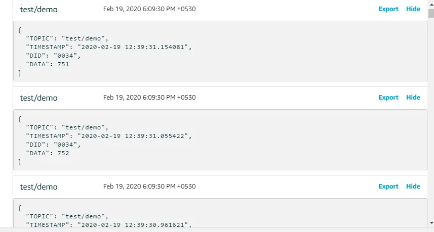
In this post, I’ve shown you how to connect your Load Cell to AWS IoT Core over MQTT on port 8883 and sniffing data from PLC. If you have had a constraint in the past to open port 8883 in your corporate firewalls, you can now use a standard port for HTTPS traffic (443) to send your messages over MQTT to AWS IoT Core endpoint.
In next part, we are going create AWS IoT Rule to forward data to Kinesis Data Stream. Also, to setup backend and frontend to show real time graph based on sensor data.
Hope you are doing well. Goodbye for now. Let's meet in next part of this project.


